
Beginner's Guide to the Basic Electrical Circuit

Introduction
Have you ever thought about how your phone gets charged, how your lights come on, or how your computer turns on and hums to life? The answer is all about the unseen paths of electricity- the basic electrical circuit. The basic electric circuit is the foundational principle used in almost every electronic device we interact with in our lives.
You can think of it as the circulatory system of electronics- just like blood flows through a body, energy flows through its circuits to support our modern lives. Examining the electrical circuit is important not only for electrical engineers, but also for anyone working in the amazing world of technology. Now let's define this word and look at this important concept while diving into the heart of electronics.
What is a Basic Electrical Circuit?
A basic electrical circuit consists of a conductive path that allows electric charge to continuously flow in a complete, closed loop. Consider a water park with slides and pools. If the water continues to flow, the slides and pools will work properly, this is typically accomplished by creating a continuous path for the water. Similarly, in an electrical circuit, electrons are charged particles which need a continuous loop to travel from a source of electrical energy, and to a device that uses the electrical energy, and then back to the source of electrical energy. Without this closed loop, the flow of electricity is interrupted, and the circuit won't function.
Understanding the Definition
A basic electrical circuit can be defined as a pathway of electrical components that are connected to provide one or more closed loops that allow for the movement of electric charge. The pathway usually consists of a power source (like a battery or generator), a conductive pathway (typically wires), and a load (any device that uses the electrical energy of the circuit, such as a light bulb or a resistor). The basic idea is that you maintain a continued flow of electrons that is created by the voltage difference of a power source.
Essential Components of a Basic-Electrical-Circuit
Every basic-electrical-circuit, no matter how simple, consists of a few essential elements:
-
Power Source: The source of electrical energy that drives the circuit. Examples of sources of electrical energy include batteries (DC source) and AC mains (AC source). Power sources create a voltage difference that acts as the "pressure" that drives the electrons through the circuit.
-
Conductive Path: These wires or other materials are connected to provide a pathway for the electrons to flow. Copper is often the preferred conductor in wiring due to its excellent conductivity.
-
Load: Loads are components that take electrical energy and perform a task, such as light bulbs (turning electrical energy into light and heat), resistors (dissipating energy as heat), and motors (turning electrical energy into mechanical energy).
-
Switch (Optional, but common): A switch is a device to open or close the circuit and control electrical flow to the load. When the switch is open, the circuit is interrupted, and current does not flow. When the switch is closed, the circle is complete, and current can flow.
Types of Circuits
Basic electrical circuits can be considered by how the components are connected. The two basic types are:
-
Series Circuits: In a series circuit, components are connected end-to-end in a single pathway. The same current will flow through every component in the circuit. If there is a break in any part of the circuit, the entire circuit will not work. For example, consider Christmas lights all strung together in a line. When one bulb goes out, the entire string goes out.
-
Parallel Circuits: In a parallel circuit, components are connected across each other, creating several paths for the current to travel through. Each component has its own branch and is connected to the power source independently. If one branch becomes faulty, the other branches will still function. Most of the wiring in a house is parallel, so if an appliance malfunctions, it does not power down the whole house.
For more complicated circuits, series and parallel connections are often combined.
Understanding Circuit Diagrams
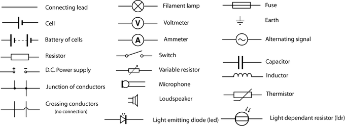
When corresponding a visual representation of an electrical circuit, engineers and technicians will use a circuit diagram. The standard symbols engineers and technicians have created will represent electrical components. It is important to have a general understanding of these standard electrical symbols so that they can properly interpret and design circuits.
Common symbols include:
-
A straight line - a wire
-
A circle with "+" and "-" in it - a DC voltage source (battery)
-
A circle with a wave shape inside it - AC Voltage Source
-
A zig-zag line - a resistor
-
A circle with an "X" inside it - a light bulb
-
Several types of symbols exist for switches.
Learning how to read a circuit diagram is a basic prerequisite for understanding how an electrical circuit is wired and operates.
Key Electrical Quantities in a Electrical Circuit
Before you can appreciate how an electrical circuit works, you need to understand three basic electrical quantities:
-
Voltage (V): Also called electrical potential difference, voltage is the “push” or “pressure” that makes the electrons go. Voltage is measured in volts (V).
-
Current (I): Current is the rate of the flow of electric charge. Current is measured in amperes (A).
-
Resistance (R): Resistance is the opposition to the flow of current. Resistance is measured in ohms (Ω).
These three quantities are related by Ohm's Law, a basic rule in electrical circuits:
V=IR
This simple equation says that the voltage, or potential difference across a conductor is proportional to the current through it and the resistance of the conductor. If you can understand Ohm's Law, you can analyze and design any simple electrical circuit.
Practical Applications of Basic Electrical Circuits
Basic electrical circuits are the basis of hundreds of technologies that we encounter and use every day. A flashlight made from a battery and a bulb, the wiring in our homes, and the circuit boards in your electronics all use the principles of a simple electrical circuit. Understanding these core concepts allows us to diagnose basic electrical problems, understand how the devices we are surrounded by work, and even get into more in-depth electronics.
Conclusion
The basic-electrical-circuit, while simple, is a basic principle of modern technology. It is the invisible structure that provides the flow of energy and makes things work in our world.
Understanding the basic components of the basic-electrical-circuit, the types of basic electrical circuits, and the basic electrical quantities that influence the behavior of the basic electrical circuit creates a better understanding and appreciation of the technology we see around us. If the reader has aspirations to pursue studies in applied fields such as Computer Science or Engineering at SERI, having a good foundational understanding of these basic electrical concepts allows for the benefit of knowledge and development of skills in more expansive learning.
The comprehensive programs offered at SERI recognize the importance of interdisciplinary knowledge, ensuring students are well-equipped to tackle the challenges of a technologically driven future. Learning the basic-electrical-circuit is only the first step in opening up the possibilities of the world of engineering and beyond.
Table Of Content
- Loading...